Hendrix Series 2 Coupler
Component Diagram
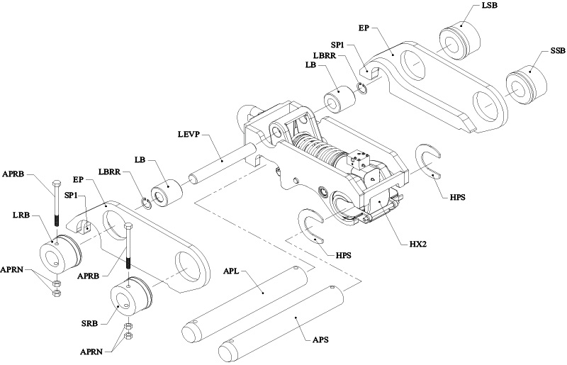
| Top Section Components | ||
| SYMBOL | DESCRIPTION | QTY |
| LSB | Link Spacing Boss | 1 |
| SSB | Stick Spacing Boss | 1 |
| EP | Ear Plate | 2 |
| SP1 | Spacer Plate | 2 |
| LBRR | Lever Boss Retaining Ring | 2 |
| LBRR | Lever Boss | 2 |
| HPS | Hook Plate Shim | 2 |
| LEVP | Lever Pin | 1 |
| APRB | Attachment Pin Retaining Bolt | 2 |
| LRB | Link Retaining Boss | 1 |
| APRN | Attachment Pin Retaining Nut | 4 |
| SRB | Stick Retaining Boss | 1 |
| APL | Attachment Pin Link | 1 |
| APS | Attachment Pin Stick | 1 |
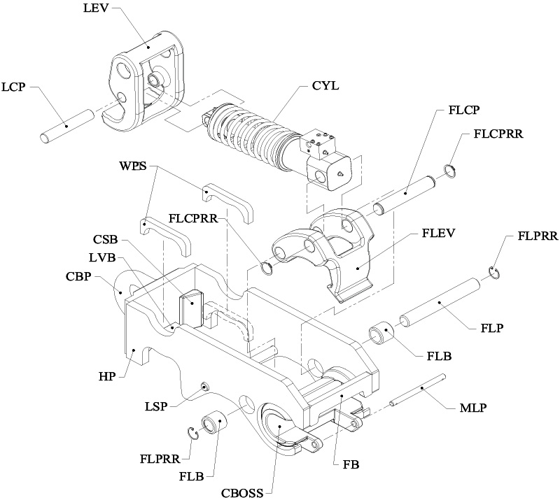
| Bottom Section Components | ||
| SYMBOL | DESCRIPTION | QTY |
| LEV | Back Lever Casting | 1 |
| LCP | Lever Cylinder Pin | 1 |
| CYL | Hydraulic Cylinder w/ Integrated Spring | 1 |
| WPS | Weld-on Pin Suooort | 2 |
| FLCPRR | Front Lever Cylinder Pin Retaining Ring | 2 |
| CSB | Comer Support Brace | 2 |
| LVB | Lever Stop Block | 1 |
| CBP | Cast Back Plate | 1 |
| HP | Hook Plate | 2 |
| LSP | Lever Stop Pin | 1 |
| FLPRR | Front Lever Pin Retaining Ring | 2 |
| FLB | Front Lever Boss | 2 |
| CBOSS | C-Boss Casting | 1 |
| FB | Front Brace | 1 |
| MLP | Mechanical Lock Pin | 1 |
| FLP | Front Lever Pin | 1 |
| FLEV | Front Lever Casting | 1 |
| FLCP | Front Lever Cylinder Pin | 1 |
View our user friendly clickable coupler catalog
FairWinds Manufacturing Coupler Catalog
You can access the catalog through the attachment above. Almost every item in the catalog is clickable for your Explore our catalog effortlessly with just a click! Simply open the attachment to access our extensive range of products. Navigate with ease by clicking on any item within the catalog – whether it’s Series 1 or Series 2, each section is clickable, directing you to the corresponding page. Need assistance with sizing? Just click on ‘Find your size’ for guidance. Enjoy seamless browsing and find exactly what you’re looking for with ease.

When calling to check on an item it is best to know your
– Dipper or stick pin diameter (A)
– Link pin diameter (B)
– Dipper width (C)
– Distance from center of dipper pin hole to center of link pin hole (D)
– Serial Number of your machine